Knowledge Base

Set initial configuration in Cisco devices
In this section learn how to set initial configuration in Cisco devices. You can also follow the video of this section on my channel on YouTube.
We have 3 modes in Cisco devices, namely:
|
Modes |
Symbols |
command |
|
User mode |
switch> |
– |
|
Privilege mode |
switch# |
enter enable in user mode |
|
Global mode |
switch(config)# |
enter config terminal or conf t to enter this mode |
In privilege mode, you can run show commands, while in global mode you can change configuration of switch.

In line 4, if you forget to write login, switch will not ask any password. So, you have to write it, to enable password in line console 0.
vty lines are using for users to connect via SSH, Telnet. In other words, to enable SSH or Telnet, you have to use these lines. By default, Cisco breaks up vty lines into two segments:
-
vty 0 – 4 (older devices)
-
vty 5- 15
New devices have more than 15 vty. Usually system administrator define 5 vty in devices.
we have two options for setting password for the privilege mode:
-
password which is in clear mode
-
secret which is encryption mode
or
if you use password instead of secret with # show running-config command you can see the clear password. To encrypt the password use this command:
now if you look at running-config , everything has become encrypted.

by default, all Cisco devices have vlan 1, so in other section will know how to make a vlan. In this code, we set IP address 192.168.1.1 with subnet mask 255.255.255.0. Then, we use command no shutdown to enable interface.
Cisco recommends all use any vlan number except vlan 1.
if you have router and you want to access your Cisco switch to router for the Internet, you have to set default gateway.
you can shutdown ports for the range of ports. For example, range of 1 to 4 is shutdown by shutdown command.
use no shutdown or no shut to enable ports
you can set a banner for a switch with motd command. After motd you have to use kind of character and it can be * + | or anything. The important matter is that both character should be the same as the code it is shown


Mistype translating domain server
In Cisco devices, if you enter a some command wrong, by default try to map it to domain name and it takes 30 sec to do that. To prevent mistype, we use this command:
if you are working with Cisco command line, you can set session timeout with these command. In these examples, we set timeout to 10 seconds.
vty line:
line console:
to save your configuration you can run these two commands:
or
Connect to Cisco devices
The first question is asked by those who are using Cisco devices for the first time is that how can I connect to Cisco devices. It needs kind of cable which is called rollover cable.

rollover cable contains RJ-45 and RS-232 and as it is demonstrated in below picture, RJ-45 is connected to switch and on the other hand RS-232 is connected to PC.
Today’s PCs usually don’t have RS-232 port. You have to buy kind of convertor for RS-232 to USB or you can use new rollover cable which is RJ45 to USB.
you can use kind of these software in PC to connect to switch through the console port. Putty is a famous software which supports SSH, Telnet, Serial.
I’ve uploaded a video in Youtube to become familiar how to connect rollover cable to switch and how to connect switch through Putty
Setup Router-on-a-Stick(Layer 2 -Layer 3)

To connect several vlans together, there is a model which is called “Router-on-a-stick“. This model has some advantages:
-
Cost effective
-
Easy to Implement
On the other hand, there are some drawbacks in this model:
-
Congestion on link(bottleneck on trunk port)
-
If router becomes down, network will down
In Switch layer2, we use router-on-a-stick to connect vlans together based on access-list we define.

As it is shown, first set an IP address for the PC0 and PC1. PC0 is on Vlan 10, while PC1 is on Vlan 20. Default Gateway of both PCs are set with the IP address of Vlan in Switch. For routing between to Vlan, Just we use “ip routing” command as it is shown in below code:
Trunk Port(Tag Port)
A trunk port is a port that is assigned to carry traffic for all the VLANs.Trunk send Untagged and Tagged information. There are two standards for Trunking:
-
ISL(Cisco)
-
802.1Q(Industry Standard) is 4 Byte which is considered without Native Vlan
Example:

In older version of Cisco devices first you have to write:
switchport encapsulation dot1q
then
switchport mode trunk
For changing Native Vlan just write:
To allow specific vlan just write:
In above-mentioned code, just vlan 10, 20, 30 allowed through trunk port
You can use switchport command with add/all/except/none
VLAN
A virtual LAN (Local Area Network) is a logical subnetwork that can group together a collection of devices from different physical LAN.
Imagine that we have different departments on your company and you want to separate each department based on their employees. So, with the VLAN concept you can create a VLAN and then assign different ports to these VLANs.

In the above picture, we have 3 departments, each of which is assigned to unique VLAN. let’s configure switch:
For viewing created VLANs, we enter this command:

VLAN 1 is a default VLAN in Cisco devices. VLAN from 1002-1005 are for other protocols. VLAN from 1006- 4094 is called Extended VLAN.
In above picture, a PC in VLAN 10 is connected to port Fa0/1 switch. So, we can write this command to access port Fa0/1 to VLAN 10:
Now, if we enter show vlan:

Now we do it for other ports:
and the result is:

By default in Cisco switches , Vlan 1 is a native Vlan. It means, untagged traffic carries in this vlan. We’ll know how to change Native Vlan.
Private Vlan
Sometimes it is necessary to have policy and separate your Vlan like below diagram. In this diagram, WWW and FTP server have communication together, so we put in community. On the other hand, SQL server shouldn’t be seen by FTP or WWW server, so, we put on isolated. In fact, there are three types of sub Vlan in Private Vlan:
-
Promiscuous: can be reached by sub Vlan
-
Isolated : can not be seen by other Vlans
-
Community: only can see community member

Imagine we want to make primary vlan for these sub Vlan. We make a Vlan “100” as a primary:
Then, make sub Vlan for www and FTP as 101 and SQL as 102
After that, we put www, FTP and SQL in primary Vlan:
Next, we assign interface to each Vlan
To use show command:
STP-PVST-RSTP-MSTP
To prevent loop between switches, Cisco uses Spanning-Tree protocol. STP is the simplest and oldest protocol which is enable by default in Cisco devices. STP is a industry standard which is used by other vendors to prevent loops in devices.
STP uses BPDU(bridge protocol data unit) to detect loops in devices. If there is any loops in Cisco devices, block redundant links. As you can see in figure 1, we have 3 switches with the same priority and in the root bridge selection, switch with the lowest priority selects as a root bridge. Now, we have the same priority, so the second feature in root bridge selection is the lowest Mac-Address. Therefore, switch A becomes root bridge and switch B and C use their shortest path to reach root bridge. This port is called root port. Then, we have selection between switch B and C, as we mentioned, switch B has the lowest Mac-Address, so it becomes Designated port and in switch C connection will be blocked.

Default priority of switch is 32768 and is multiple of 4096( between 0-61440) while, default port-priority in switch is 128 and multiple of 16.
In STP , we have 5 states, namely:
disabled, blocking(20sec), listening(15sec), learning(15sec), forwarding
It means, we have to wait at least 50 seconds until fully convergence.
We can configure switch for STP and change the priority or make a switch as primary root:
you can use show command to see the root or states of connections:
This is the same idea of STP . The only difference here is using in Vlan instead of STP. The delay in receiving BPDUs can cause problems like convergence time problems. Per-VLAN Spanning Tree (PVST) is a solution for these problems. PVST operates a separate instance of STP for each individual VLAN . So, it helps load-balancing more efficiently.
Cisco enhanced the original 802.1D specification with features such as Uplink Fast, Backbone Fast, and Port Fast to speed up the convergence time of a bridged network. In RSTP we have five states, namely:
|
STP (802.1D) Port State |
RSTP (802.1w) Port State |
|
Disabled |
Discarding |
|
Blocking |
Discarding |
|
Listening |
Discarding |
|
Learning |
Learning |
|
Forwarding |
Forwarding |
It means, by removing listening states now convergence takes on 30 seconds. To configure, simply add:

As you see in Figure 2, we have Alternate port instead of block port in RSTP. Also, RSTP can detect edge port and separate root port from edge port.
PortFast causes a switch or trunk port to enter the spanning tree forwarding state immediately, bypassing the listening and learning states.
You can use PortFast on switch or trunk ports that are connected to a single workstation, switch, or server to allow those devices to connect to the network immediately, instead of waiting for the port to transition from the listening and learning states to the forwarding state.
The most secure implementation of PortFast is to enable it only on ports that connect end stations to switches. To config it:
PortFast BPDU guard prevents loops by moving a nontrunking port into an errdisable state when a BPDU is received on that port. When you enable BPDU guard on the switch, spanning tree shuts down PortFast-configured interfaces that receive BPDUs. Cisco recommend every ports connected to endpoint devices should have BPDU guard. BPDU guard:
-
Change the interface to errdisable state
-
Prevent from receiving BPDU
To enable BPDU guard:
While, BPDU filtering allows you to avoid transmitting BPDUs on PortFast-enabled ports that are connected to an end system. When you enable PortFast on the switch, spanning tree places ports in the forwarding state immediately, instead of going through the listening, learning, and forwarding states. BPDU filtering:
-
Prevent from sending and receiving BPDU
-
Stop spanning-tree in the interface
BPDU guard and root guard are similar, but their impact is different. BPDU guard disables the port upon BPDU reception if PortFast is enabled on the port. The disablement effectively denies devices behind such ports from participation in STP. You must manually reenable the port that is put into errdisable state or configure errdisable-timeout.
Root guard allows the device to participate in STP as long as the device does not try to become the root. If root guard blocks the port, subsequent recovery is automatic. Recovery occurs as soon as the offending device ceases to send superior BPDUs.
When one of the ports in a physically redundant topology no longer receives BPDUs, the STP conceives that the topology is loop free. Eventually, the blocking port from the alternate or backup port becomes designated and moves to a forwarding state. This situation creates a loop.
The loop guard feature makes additional checks. If BPDUs are not received on a non-designated port, and loop guard is enabled, that port is moved into the STP loop-inconsistent blocking state, instead of the listening / learning / forwarding state. Without the loop guard feature, the port assumes the designated port role. The port moves to the STP forwarding state and creates a loop.
MST extends the IEEE 802.1w rapid spanning tree (RST) algorithm to multiple spanning trees. This extension provides both rapid convergence and load balancing in a VLAN environment. MST converges faster than Per VLAN Spanning Tree Plus (PVST+) and is backward compatible with 802.1D STP, 802.1w (Rapid Spanning Tree Protocol [RSTP]), and the Cisco PVST+ architecture.
MST allows you to build multiple spanning trees over trunks. You can group and associate VLANs to spanning tree instances. Each instance can have a topology independent of other spanning tree instances. This architecture provides multiple forwarding paths for data traffic and enables load balancing. Network fault tolerance is improved because a failure in one instance (forwarding path) does not affect other instances.
In large networks, you can more easily administer the network and use redundant paths by locating different Vlan and spanning tree instance assignments in different parts of the network.
MST includes some regions and each region contains Vlans. As it shown in below code, we have different instances and in each instance we have Vlans. If Vlans don’t have any instance, it goes to instance 0.
to show mst configuration:
SPAN-RSPAN
To sniff or to analyse traffic on specific port or Vlan you can use SPAN. As it is shown in Figure 1, we want to have traffic of FastEthernet0/1 on port FastEthernet0/10. So, simple we can define monitor session for interface FastEthernet0/1 as a source and FastEthernet0/10 as a destination.

You can define a receive, transmit or both in monitor session:
SW(config)#monitor session 1 source int fa0/1 rx | tx | both
This is exactly the same scenario of SPAN, but here we remotely monitor a port in switch. First, you have to define separate Vlan between two switches. Then, you can specify source and destination.

NetFlow
NetFlow is a networking analysis protocol that gives the ability to collect detailed information about network traffic as it flows through a router interface. NetFlow helps network administrators answers the questions of who (users), what (application), when (time of day), where (source and destination IP addresses) and how network traffic is flowing.

+NetFlow Monitor: a component applied to an interface and collects information about flows. Flow monitors consist of a record and a cache. You add the record to the flow monitor after the flow monitor is created. In the topology above, we can apply the NetFlow Monitors to the s0/0, Fa0/0 and Fa0/1 interfaces of the router to collect traffic information of these interfaces + NetFlow Exporter: aggregates packets into flows, stores IP flow information in its NetFlow cache and exports them in the form of flow records to the NetFlow collector + NetFlow Collector: collects flow records sent from the NetFlow exporters, parsing and storing the flows. Usually a collector is a separate software running on a network server. NetFlow records are exported to a NetFlow collector using User Datagram Protocol (UDP) + NetFlow Sampler: used to reduce the number of packets that are selected for analysis. It is applied to a NetFlow Monitor to reduce the overhead load because the number of packets that the flow monitor must analyze is reduced. But notice that the accuracy of the information stored in the flow monitor’s cache is also reduced correspondingly.
When packets arrive at the NetFlow Exporter, each of them is inspected for one or many IP packet attributes. These attributes are used to determine if the packet is unique or similar to other packets. If it is similar then it is classified as in the same flow.
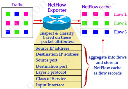
There are seven key IP packet attributes that can be used by NetFlow to classify packets into separate flows: + IP source address + IP destination address + Source port + Destination port + Layer 3 protocol type + Class of Service (or Type of Service – ToS) Byte + Input (Router or switch) interface
Other attributes can be also used and they are called non-key attributes such as timestamps, packet and byte counters, TCP flag information…
After inspecting these attributes, the NetFlow Exporter condenses them into flow records and save in a database called the NetFlow cache. These flow records can also be exported to a NetFlow Collector.
How to view NetFlow data
There are two main methods to view NetFlow data:
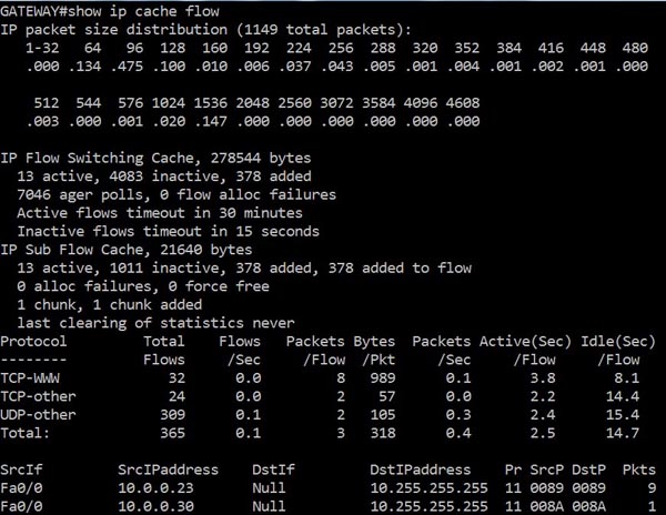
+ Command Line Interface (CLI): Because the NetFlow cache is a part of the NetFlow Exporter so we can view this cache directly via the Command-Line-Interface (CLI), which is very useful for troubleshooting, with the “show ip cache flow” command. An example output of this command is shown below:
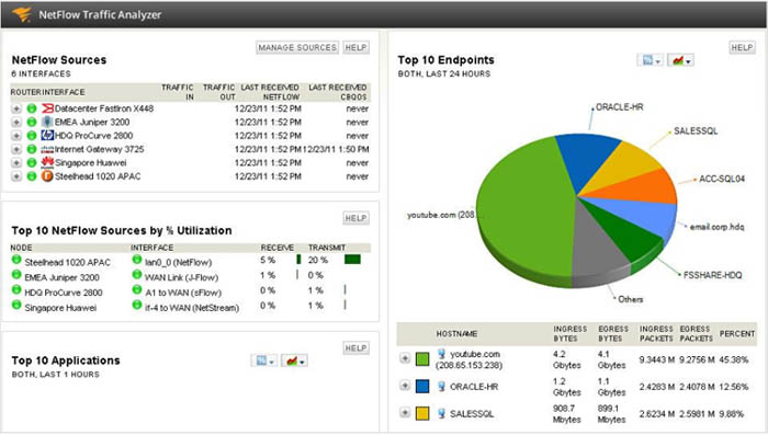
+ A NetFlow reporting tool: there are many tools that can collect NetFlow packets sent to the NetFlow Collector and display a comprehensive view. Below is an example of what SolarWinds NetFlow Traffic Analyzer can analyze:
Version 1: the original format supported in the initial NetFlow releases. Versions 2, 3 and 4 were not released. Version 5: an enhancement that adds Border Gateway Protocol (BGP) autonomous system information, flow sequence numbers and a few additional fields. This is the standard and most common NetFlow version. Only support IPv4. Version 6: similar to version 7 Version 7: Cisco-specific version for Catalyst 5000 series switches but not compatible with Cisco routers Version 8: choice of aggregation schemes in order to reduce resource usage Version 9: support flow-record format and it is known as Flexible NetFlow technology. NetFlow version 9 includes a template to describe what is being exported. It supports extensible file export format to enable easier support. It also supports additional fields & technologies such as MPLS, IPv6, IPSec, NBAR protocols, Multicast, VLAN ID…
In general, the two most important NetFlow versions are Version 5 and Version 9 which we will learn how to configure them.
|
Note: NetFlow version 5 only supports monitoring inbound statistics using the “ip flow ingress” command while NetFlow v9 allows to monitor traffic leaving each interface via “ip flow egress” command. |
To configure NetFlow version 9 (Flexible NetFlow), we need to configure three components: 1. Flow Record 2. Flow Exporter 3. Flow Monitor
The following configuration enables NetFlow version 9 on Fa0/1 interface and export to a NetFlow collector at 10.1.1.1 on UDP port 2055.
1. Configure the Flow Record:
2. Configure the Exporter:
3. Configure the Exporter:
4. Apply to an interface
SNMP(V1-2-3)
SNMP is an application-layer protocol that provides a message format for communication between managers and agents. The SNMP system consists of:
-
an SNMP manager,
-
an SNMP agent,
-
and a MIB.
The SNMP agent contains MIB variables whose values the SNMP manager can request or change. A manager can get a value from an agent or store a value into the agent. The agent gathers data from the MIB, the repository for information about device parameters and network data. The agent can also respond to a manager’s requests to get or set data.
An agent can send unsolicited traps to the manager. Traps are messages alerting the SNMP manager to a condition on the network. Traps can mean improper user authentication, restarts, link status (up or down), MAC address tracking, closing of a TCP connection, loss of connection to a neighbor, or other significant events.
|
Model |
Level |
Authentication |
Encryption |
Result |
|
SNMPv1 |
noAuthNoPriv |
Community string |
No |
Uses a community string match for authentication. |
|
SNMPv2C |
noAuthNoPriv |
Community string |
No |
Uses a community string match for authentication. |
|
SNMPv3 |
noAuthNoPriv |
Username |
No |
Uses a username match for authentication. |
|
SNMPv3 |
authNoPriv |
Message Digest 5 (MD5) or Secure Hash Algorithm (SHA) |
No |
Provides authentication based on the HMAC-MD5 or HMAC-SHA algorithms. |
|
SNMPv3 |
authPriv (requires the cryptographic software image) |
MD5 or SHA |
Data Encryption Standard (DES) or Advanced Encryption Standard (AES) |
Provides authentication based on the HMAC-MD5 or HMAC-SHA algorithms. Allows specifying the User-based Security Model (USM) with these encryption algorithms: DES 56-bit encryption in addition to authentication based on the CBC-DES (DES-56) standard. 3DES 168-bit encryption AES 128-bit, 192-bit, or 256-bit encryption |
configuring SNMPV2 is so simple, just write :
ro means read only and rw means read/write
configuring SNMPV3 needs three steps:
1- Defining View
iso means everything in MIB.
2- Defining Group
3- Defining User
PRTG is really good tool for grabbing information from devices which are working with SNMP. You can download this software and connecting around 100 sensors are free. In other word, you can use it for small business.
1-First, Add a New Device, and IPV4 address.

2- Second, Select SNMP version, type of Authentication(SHA-MD5) and enter your username and password.

3- Third, enter encryption type and Pre-shared key.

4- Add your desire sensor, there are alot of sensors for different devices, for example I add ping to this device.

TACACS and RADIUS
TACACS+ and Radius is a security application that provides centralized validation of users attempting to gain access to a router or network access server. In Table 1 main difference between TACACS and Radius are mentioned:
|
Feature |
TACACS+ |
RADIUS |
|
Encryption |
Packet fully encrypted |
Password encrypted |
|
Protocol |
TCP |
UDP |
|
Standard |
Cisco |
Industry |
|
AAA |
Separate AAA |
Combine AAA |
To configure Radius or TACACS+ , first we define a new model and then we use dot1x authentication:
Etherchannel(layer2-layer3)
EtherChannel is a port link aggregation technology or port-channel architecture used primarily on Cisco switches. It allows grouping of several physical Ethernet links to create one logical Ethernet link for the purpose of providing fault-tolerance and high-speed links between switches, routers and servers(wiki).

There are two protocols in ether-channel:
-
PAGP (Cisco proprietary )
-
on
-
auto
-
desirable
-
-
LACP(Industry Standard)(802.3AD)
-
on
-
active
-
passive
-
To implement layer 2 PAGP:
To implement layer 2 LACP:

In layer3, we use virtual ip address in port channel to define PAGP:
Static Routing
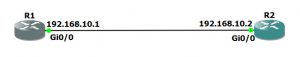
Routing is a huge concept in Cisco and I don’t want to dive into routing protcols concept, but I want to focus on simple routing which is called Static Routing. To know this concept look at this diagram. In static routnig, to reach from network1 to network2 , you need to define networks in router1 and router 2.

R1 knows just their interfaces, for reaching to network 192.168.3.0/24, we use interface 192.168.2.2, therefore we write:
R2 knows just their interfaces, for reaching to network 192.168.1.0/24, we use interface 192.168.2.1, therefore we write:
DHCP
Dynamic Host Configuration Protocol (DHCP) is a protocol to dynamically giva an IP address to different devices. In cisco, defining DHCP is following these steps:
-
Define DHCP exclude-address: We separate unwanted address in DHCP
-
Define DHCP Pool : We define DHCP pool which is assigned to clients
-
Define network, dns-server and default router
Port Security
In Cisco switches, you can limit PCs based on their Mac-address. Port security enhances the security in Cisco devices
Let’s implement a scenario to learn more about port security:
Senario 1: In company A, we want to define port-security to learn mac-address of all PCs on the nework and maximum each port has to learn maximum two mac-address. In a case of violation, ports should shutdown immediately.
port security voilation has three modes:
-
shutdown: This is a default mode. It’ll shutdown the interface.
-
protect: Allow traffic from valid mac-address but block traffic from invalid.
-
restrict: Assist with troubleshooting by keeping count of voilations.
You can define static mac-address with this command:
In real scenario, network administrators define auto recovery for port security. It means in case of violation, ports automatically enable timer to recover from psecure violation disable state:
also we can define timer interval(second), to recover automatically:
You can use these commands to see port security:
SSH
SSH, also known as Secure Socket Shell, is a network protocol that provides administrators with a secure way to access a remote computer.
To have a secure connection to Cisco devices, we don’t use Telnet. Because Telnet sends the password in plain Text. If you use kind of sniffer tools such as Wireshark, you can see exact password is passing to the device. So, for having secure connection all system administrators use SSH.
There are 5 steps for creating SSH connection, which are namely:
-
Create a hostname
-
Create a domain name
-
Generate RSA key
-
Create a local account
-
Allow SSH in vty line
In line 4, length of RSA key depends on the device. Some devices support more than 1024 or 2048.
In line 6, you can use password or secret, as I told you in previous section, secret encrypts your password in running-config, but password is shown in clear text.
In line 8, you can select telnet, ssh or both of them to allow in vty line. In other words, if you select all, ssh users and telnet users can connect through vty line
VTP(Vlan Trunking Protocol)
VTP is a layer 2 messaging protocol which is a Cisco proprietary protocol that propagates the definition of Virtual Local Area Networks (VLAN) on the whole local area network. VTP minimizes misconfigurations and configuration inconsistencies that can result in a number of problems, such as duplicate VLAN names, incorrect VLAN-type specifications, and security violations.
There are three versions of VTP, namely version 1, version 2, version 3. All feature of 3 versions of VTP is shown in Table1
|
VTP V1 |
VTP V2 |
VTP V3 |
Feature |
|
* |
VTP password |
||
|
* |
Private Vlan |
||
|
* |
Extended Vlan |
||
|
* |
Token Ring Support |
There are three main modes in VTP:
-
Server : This is a default mode of VTP. You can create, modify, and delete VLANs and specify other configuration parameters (such as VTP version and VTP pruning) for the entire VTP domain. VTP servers advertise their VLAN configuration to other network devices
-
Client: VTP clients behave the same way as VTP servers, but you cannot create, change, or delete VLANs on a VTP client.
-
Transparent: VTP transparent network devices do not participate in VTP. A VTP transparent network device does not advertise its VLAN configuration and does not synchronize its VLAN configuration based on received advertisements. However, in VTP version 2, a transparent network device will forward received VTP advertisements from its trunking LAN ports. In VTP version 3, a transparent network device is specific to an instance.
Example:

We want to make a Vlan in Switch 1 and change its mode to server mode. Between Switch 1 and Switch 2, we use trunk port and then set Switch 2 mode for VTP to client.
to see status of VTP:

Now if you check, switch2 , you can see Vlan 10, 20 are made automatically.
in VTP V3, you can define password VTP. In doing so, just switches with the same password can talk eachother.
VTP pruning enhances network bandwidth use by reducing unnecessary flooded traffic, such as broadcast, multicast, unknown, and flooded unicast packets. VTP pruning increases available bandwidth by restricting flooded traffic to those trunk links that the traffic must use to access the appropriate network devices. By default, VTP pruning is disabled.


As you can see in above pictures, traffic with and without VTP Pruning is demonstrated. To enable VTP pruning:
To enable VTP V2 or V3, you have to write:
Access-list(Standard - Extended)
In Cisco we have two types of access-list:
-
Standard
-
It’s based on source address
-
It uses lower process utilization
-
-
Extended
-
It’s based on source/destination and port number
-
It uses high process utilization
-
We define access-list only on routers or layer3 switches. You can’t define access-list on layer 2 switches

Imagine in router 2, we want to deny any packets come from network 192.168.3.0/24. To prevent these packet based on standard access-list just pay attention to source:
In this command, first, we define access-list and write it as 10. This number should between 1 to 99 . Then, we deny every source address in network 192.168.3.0/24. In access-list, we always use wildcard mask instead of netmask. To know wildcard mask, just substract 255.255.255.255 from network mask , the result shows wildcard mask.
Next, we permit others to access network. If you forget to write line 2, all network will be down. Because you forbid any connections from router 2.
After that, we have to associate access-list to router interface. We have inbound and outbound, in this example, we are entering from network 192.168.3.0/24 to router 2. So, we write access-list in inbound of router.

The best practise we can bring here, is our previous router-on-a-stick. In above example, we have two PCs which can communicate together through router 0. Switch 0 is connected to Router0 through trunk port. PCs IP address is:
-
PC0
-
IP Address: 192.168.10.2
-
Netmask: 255.255.255.0
-
Default Gateway: 192.168.10.1
-
-
PC1
-
IP Address: 192.168.20.2
-
Netmask: 255.255.255.0
-
Default Gateway: 192.168.20.1
-
Now, we want to forbid every packet goes from vlan 10 to vlan 20 and vice versa. So, we can define access-list based on source and destination. In extended access-list, you have to follow these rules:
1- Protocol –> Source Address–> Destination Address –> Port
2- Extended access-list starts from 100-199
This is for Vlan 10 which bans every packet from network 192.168.10.0/24 to 192.168.20.0/24. We define protocol, IP. It means, any related protocol to IP such as ftp, web, ….. In other words, I ban all protocols of IP.
For Vlan 20, we have:
Then, we access above-mentioned access-list to int fa0/0.10 and fa0/0.20:
There are different scenarios in access-list and it can be permit and deny or any protocol such as ftp, web. Imagine in above example just we want to deny telnet and ssh. Then, we write:
To know, what we write and how access-list work, just write :

You can define, named access-list like numbered access-list in section 1-2 and 1-1. I write previous example in named access-list:
As you can see, everything is the same as numbered access-list. In real work, network engineers prefer using named access-list rather than numbered access-list
RIP, EIGRP, OSPF
RIP
- Maximum hop count 15
- RIP ( 30 Sec update to other routers)
- Doesn’t analyse traffi
- Distance Vector
- RIPng( send through hex to other routers FF2::9)
EIGRP
- Only to Cisco Protocol
- Distance vector
- Analyses traffic
- Autonomous system limitation
- Pays attention to bandwidth too. up to 15 routers is good
in fact, with the same autonomous number routers can speak together. if autonomous number of one of routers is different. The network will be down.
OSPF
- Larger Network
- Link state(Dikestra- Shortest path first)
- Very scalable
- Uses area instead of autonomous
- Each area no more 15 routers
Configure rip V2
conf t
(config)# router rip
(config)# version 2
(config)# net 10.1.1.4
(config)# net 192.168.1.0
(config)# no auto-summary
Important command
conf t
(config)# do sh start ( with do that is not necessary to be out)
(config)# do sh ip int br ( good)
(config)# do sh protocols( show protocols )
(config)# do sh controllers ( hardware information)
(config)# do sh ip rip
(config)# do sh ip route
debug ip rip( behind scence)
no debug ip rip
Set IPV6 for
conf t
(config)# ipv6 unicast-routing ( for writing ipv6)
(config)# int f0/0
(config)# ipv6 address 2001:3200….
For IPV6
conf t
(config)# ipv6 router rip 1
(config)# int f0/0
(config)# ipv6 rip 1 enable
sh ipv6 route
RIP timer
router rip timers basic 30(interval between update) 180(Invalid) 180(Holddown) 240(Flush)
conf t
(config)# router eigrp 100(autonomous number can share update in the same autonomous system)
(config)# net 192.168.10.10
(config)# net 10.10.10.0.1
(config)# no auto-summary
conf t
(config)# router ospf 100(process ID)
(config)# net 192.168.1.0 0.0.0.255(inverse subnetmask=wildmask card) area 0
(config)# net 10.1.1.4 0.0.0.3 area 0
show ip ospf neighbour
Configuring WPA2 with AES or TKIP and PSK on Cisco Aironet 1140 Access Points
First of all, we have to create an SSID profile. You can do this with the command dot11 ssid ssid. Let’s make a SSID with the name ‘CiscoTalkWireless’.
|
1
2
|
ap(config)#dot11 ssid CiscoTalkWirelessap(config-ssid)# |
Next, we can configure the SSID properties. In this example, we want to use open authentication with key management provided by WPA2. In addition, I want to broadcast this SSID. This makes its easier for users to connect to your network. This is especially useful for guest wireless networks. While in SSID configuration mode:
|
1
2
3
4
|
ap(config-ssid)#authentication openap(config-ssid)#authentication key-management wpa version 2ap(config-ssid)#guest-modeap(config-ssid)#wpa-psk ascii CiscoTalkTutorials! |
The configuration is pretty self-explanatory.
authentication open enables open authentication.
authentication key-management wpa version 2 configures this SSID to use WPA2. If you leave off version 2and enter authentication key-management wpa, you are configuring the SSID with WPA.
guest-mode enables SSID broadcasting.
wpa-psk ascii sets the pre-shared key for the SSID.
Now with the SSID profile configured, we need to specify an encryption method. Let’s enter interface configuration mode on Dot11Radio0:
|
1
2
|
ap(config)#interface Dot11Radio0ap(config-if)# |
There are a few options you can use for encryption. You can also use AES, TKIP, and WEP. I strongly advise against using WEP and recommend AES over TKIP.
For AES:
|
1
|
ap(config-if)# encryption mode ciphers aes-ccm |
For TKIP:
|
1
|
ap(config-if)# encryption mode ciphers tkip |
Now with the encryption method in place, let’s assign the SSID:
|
1
|
ap(config-if)# ssid CiscoTalkWireless |
By default and as a security measure, all new Cisco Access Points ship with the radios turned off. So as a final step, let’s enable the radio:
|
1
|
ap(config-if)# no shutdown |
By default, Cisco access points select the least congested wireless channel. As soon as you enable the interface, the access point will scan and assign itself an appropriate channel. Once the channel selection process is complete, you should now have a working wireless network! You can verify connected clients by using the show dot11 associations command:
|
1
2
3
4
5
6
7
8
9
|
ap#show dot11 associations802.11 Client Stations on Dot11Radio0:SSID [CiscoTalkWireless] :MAC Address IP address Device Name Parent State100b.bbbd.e248 10.10.83.110 ccx-client CiscoTalk-PC self Assocap# |
My next post will be a tutorial on how to configure multiple SSIDs using different VLANs on a single access point.
Cisco ASA FirePOWER Services: how to install FMC?
Technology: Network Security
Area: Next Generation Firewalls
Vendor: Cisco
Software: 8.X, 9.X, FMC 5.X, 6.X, SFR module 5.X , 6.X
Platform: Cisco ASA, Firepower Management Center VM
Firepower Management Center installation steps
1. Deployment from OVF
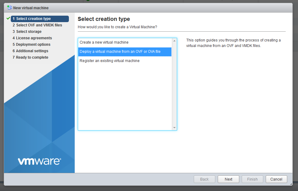
2. Assign the hostname for VM
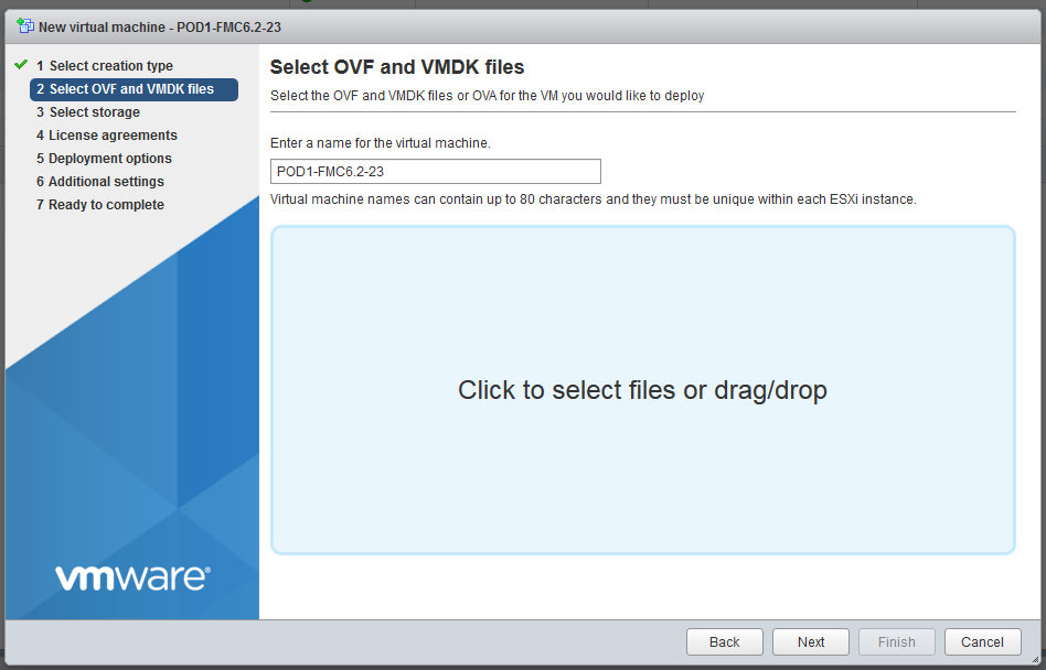
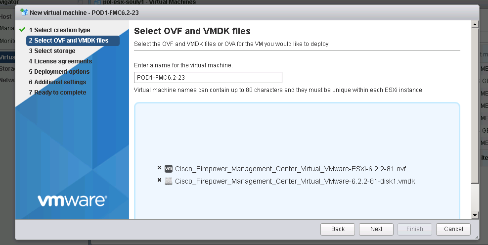
3. Choose the right ovf and vmdk files
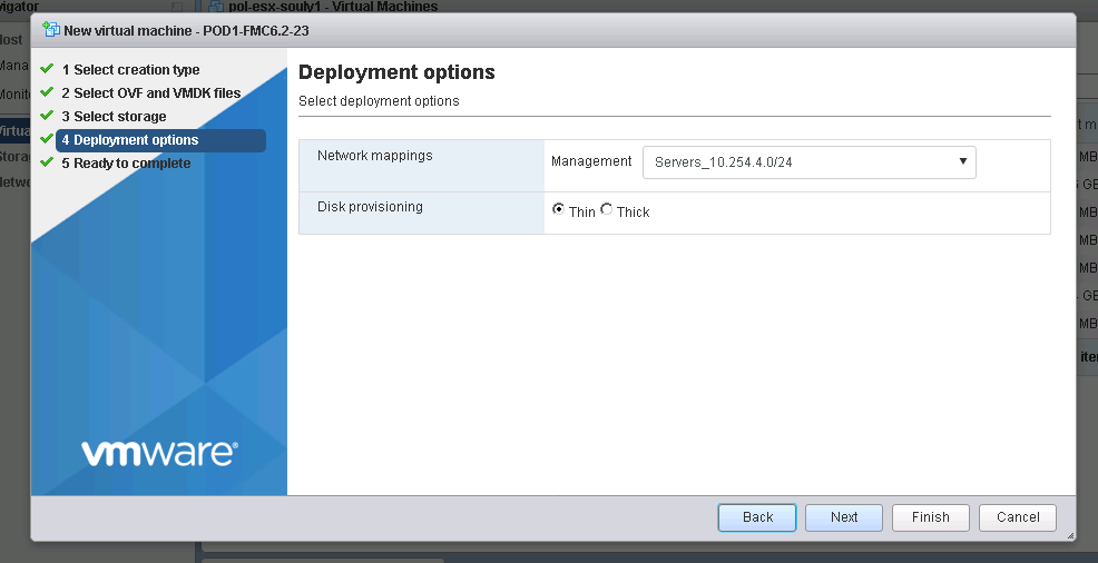
4. Select proper vNIC (the one you will use for management purposes and communication with the sensor) and disk provisioning type
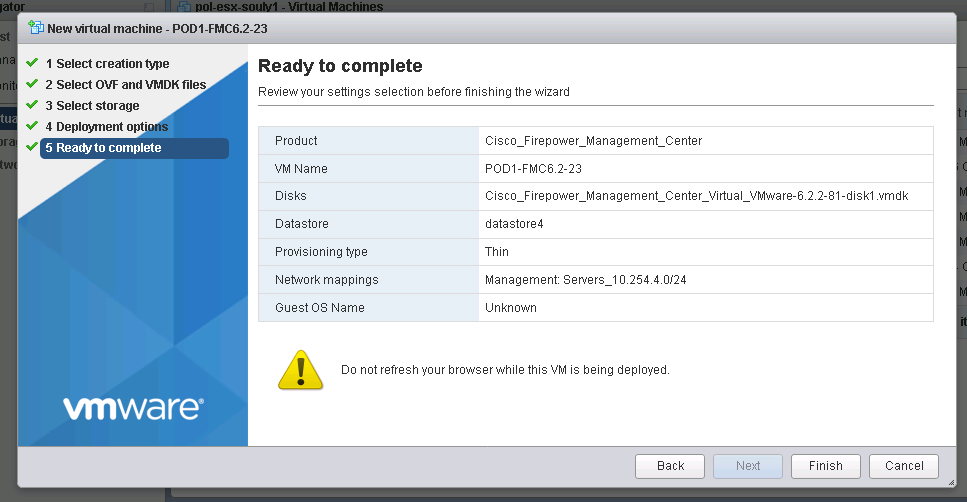
5. VM Deployment is finished
6. VM starts the installation
Note: The Cisco Firepower Management Center Virtual instance then appears under the specified data center in the Inventory. Booting up the new VM could take up to 30-40 minutes.
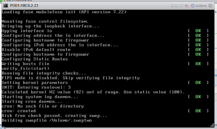
7. After about 20 minutes you will see the system first initialization message
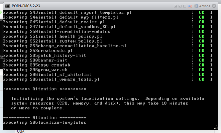
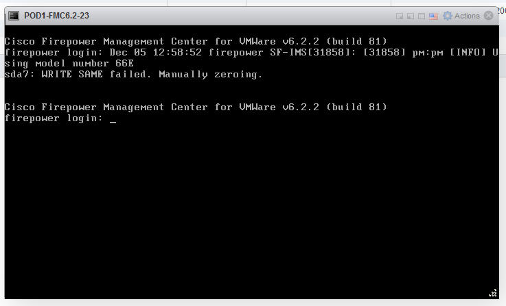
8. After installation is complete, the firepower login prompt appears.
Note: A message “WRITE SAME failed. Manually zeroing.” may appear after the system is booted up for the first time. This does not indicate a defect, it correctly indicates that the VMware storage driver does not support the WRITE SAME command. The system displays this message, and proceeds with a fallback command to perform the same operation
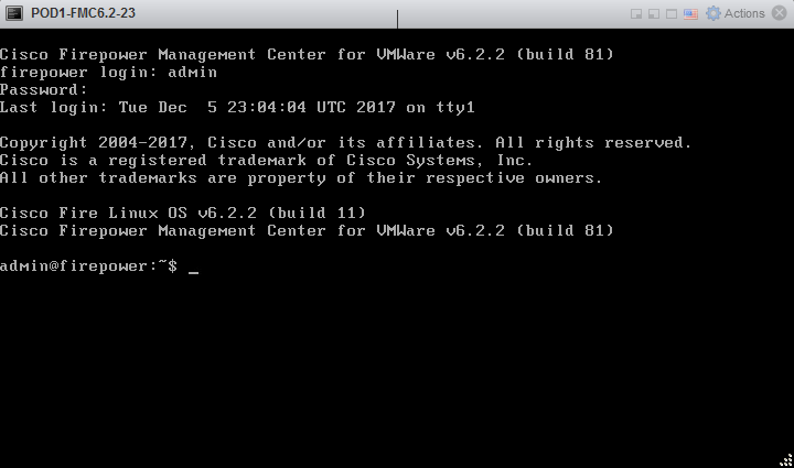
Default user and password for version 6.x FMC and later
- Username: admin
- Password: Admin123
9. First login and setup
10. Setup of FMC – CLI (you might be prompted for sudo password then provide the same password as used when loging in)
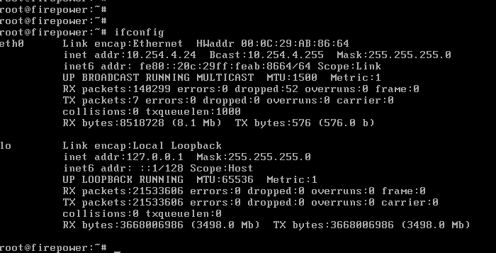
11. Checking the interfaces on FMC and ensuring proper addressing:
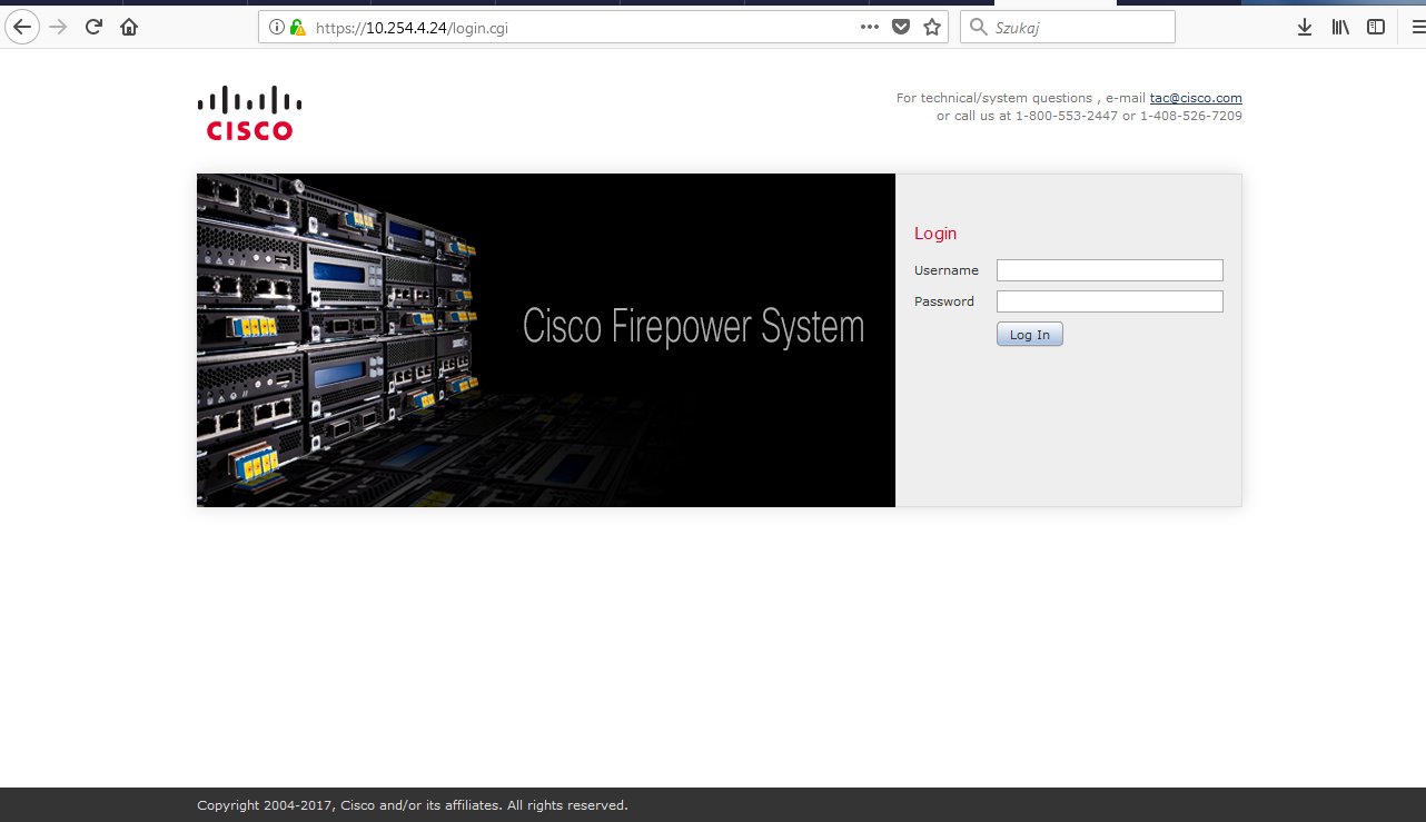
12. First GUI login comes up after typing the IP address (or FMC’s FQDN) set during installation. To login use exactly the same credentials as used for CLI login.
Migrating ASA to FTD
For this post, we will be discussing migrating an ASA with FirePOWER services to a Firepower Threat Defense (FTD) image on an ASA 5506-X appliance. At a high level, you reimage the ASA unit with a FTD then use the migration tool (if you have an existing ASA configuration) to import the ASA configuration into the new FTD configuration.
Let’s start with some of the pre-requirements for the re-image process. First, backup the ASA configuration along with the ASA, ASDM, and FirePOWER software. You can do this with a full backup through the ASA ASDM or CLI. Also, backup any license files or keys you may have for the ASA and make sure the ASA’s ROMMON version is 1.1.8 or greater (if not then upgrade it). Secondly, download the FTD boot image and install package software (the file names will vary depending on ASA model). Lastly, make sure you have console access to your ASA unit.
Now let’s go through the ASA to FTD re-image process. You can refer to this link from Cisco for details of this process and I will refer back to it throughout this blog: https://www.cisco.com/c/en/us/td/docs/security/firepower/quick_start/reimage/asa-ftd-reimage.html.
Step 1: Reboot the ASA and get into the ROMMON prompt. You can break into ROMMON by pressing ESC when prompted to during the reboot.

Step 2: Setup a TFTP server on your laptop or LAN then while in ROMMON, configure the ASA interface with an IP address that is accessible by the TFTP server. You will use this to load the FTD boot image into the ASA unit. The interface you configure does vary depending on the ASA model, so check the link in the beginning of the section for details.
For this lab, I’m using an ASA 5506-X so it will not allow me to choose an interface. All interface configuration is applied to the management interface. Also, the TFTP server is on my laptop so I set the gateway as the same as the TFTP server address.
Commands in ROMMON to run at this step:
- rommon #0> address <ip address>
- rommon #1> server <tftp server IP address>
- rommon #2> gateway <gateway IP address>
- rommon #3> file <boot image file name>
- rommon #4> set
Step 3: Once the interface is configured, make sure you can ping the TFTP server to verify network connectivity then download the FTD boot image.

Commands in ROMMON to run at this step:
- rommon #5> sync
- rommon #6> tftpdnld
After the ‘tftpdnld’ command is ran the FTD boot image will download and reboot the ASA into the FTD Boot CLI
Step 4: Setup an HTTP or FTP server on your laptop or network for to install the FTD systems install package to the ASA. In the FTD boot CLI, run the ‘setup’ command and it step you through configuring network settings for the install.

Step 5: Once the ASA’s network settings is configured then install the system image using the ‘system install’ command.
Commands for this step:
system install [noconfirm] http://<ip address of tftp server>/<ftd system image file name>
The noconfirm allows you not to respond to confirmation messages from during the install.

The install can take some time so grab a cup of coffee and be prepared to wait. Once the install is done, the ASA will reboot and bring up the FTD CLI prompt.
![]()
You have now re-imaged an ASA unit with a FTD image. At this point you can log into the on-box management GUI, Firepower Device Manager (FDM), or you can add the ASA to the Firepower Management Center (FMC) as you would normally add a Firepower device. For this blog, I will be using FDM to manage FTD.
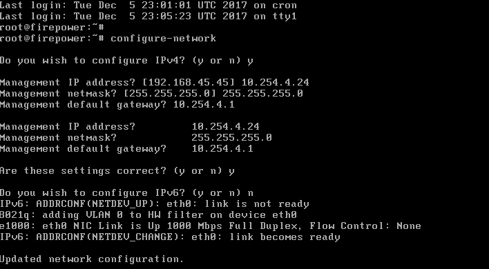
Lastly, let’s confirm we can log into the FDM portal. By default, FTD assigns the management interface for the ASA unit with an IP address of 192.168.45.45 and has DHCP server enabled on it. You can plug your laptop into the management port and receive an IP address on that subnet.
Browse to https://192.168.45.45 and log into FDM with the default username and password, admin/Admin123.

After you log into FDM, you will be prompted to change the password and accept the EULA. It will then run you through a wizard for initial configuration.

For the last part of this blog, we will look (at high-level overview) into the ASA to FTD configuration migration tool. If you have an existing ASA configuration that you need to migrated to FTD, you can use this tool to help migrate some of the ASA configuration to FTD. There are some caveats to this and we will discuss them in a moment after we go over the migration process.
For the configuration migration, you will first want to back up the ASA configuration file in a .cfg or .txt format first then make sure the ASA code level is at least on 9.1 version and ASDM on version 7.1. The migration tool is a feature you enable on a Firepower Management Console (FMC) VM, which should not be a Production FMC since it only allows to use the migration tool features. If it is done a production VM, the FMC will require a re-image to be able to in order to un-install the migration tool. Make sure the migration tool is the same major and minor release as the production FMC that you will import the configuration into. For example, if your FMC is running 6.2.0.2 then the version of FMC that the migration tool is running on needs to be 6.2.0.2 as well. You will then run the ASA configuration file through migration tool and download the .sfo file, then import that into the Production FMC. You can use the imported configuration to set up an Access Control Policy to apply to the FTD device.
Now to the caveats and limitation of what ASA configuration parameters the tool converts. Here is a list of what ASA configurations the tool supports:
- Extended access rules
- Twice NAT statements
- Object NAT statements
- Network objects/groups and service objects/groups that are associated with extended access rules and NAT statements which the tool coverts
Here is a list of the tool’s limitations:
- It migrates only ASA configurations. It does not migrate FirePOWER services configuration, these policies will have to be migrated manually.
- It can support up to 2000000 total access rules, if there is more ACEs than what is stipulated then the migration will fail.
- It will migrate ACLs that are applied to interfaces only. You can check on which ACLs are applied to interfaces by running a ‘show run access-group’ command.
- The tool only coverts objects that are used in ACLs that are applied to interfaces and NAT statements migrated. It does not migrated objects alone.
- It does not migrate EtherType or WebType ACLs, ACEs that use host address name aliases (defined by the ‘name’ command), and ACEs that use default service objects.
- It will covert, but disable ACEs that include the following: time-range objects, Fully-qualified domain names (FQDN), Local users or user groups, Security group (SGT) objects, and Nested service groups for both source and destination ports. It disables these rules since FTD does not have an equivalent functionality for these parameters. For a disabled rule, you can edit it to meet supported FTD configuration.
As you can see the FTD migration tool will aid you in migrating an existing ASA configuration to an FTD deployment. Keep in mind that it will not convert everything in the ASA configuration and there will be at some manual migration, but the tool will save you some time and provide you with a good starting point for your migration!
source: egroupcloud.com
DVTI on Hub-Spoke IKEV2
R1
—————–
(config)#crypto pki certificate map CAMP 1
#issuer-name co talebi
(config)# default crypto ikev2 proposal
(config)# crypto ikev2 proposal default
# encryption aes-cbc-256
# integrity sha256
# group 14
(config)# default crypto ikev2 policy
(config)# crypto ikev2 profile IKEV2-Profile
# identity local dn
# match certificate CMAP
# authentication remote rsa-sig
# authentication local rsa-sig
# pki trustpoint Trusted-cA
# virtual-template 1
(config)# default crypto ipsec transform-set
(config)# crypto ipsec transform-set default esp-gcm 256
(config)# default crypto ipsec profile
(config)# crypto ipsec profile default
(config)# set ikev2-profile IKEV2-Profile
(config)# interface virtual-template 1 type tunnel
#ip unnumbered loop 0
#tunnel source eth0/0
#tunnel mode ipsec ipv4
#tunnel protection ipsec profile default
#ip ospf 1 area 0
R2
—————–
(config)#crypto pki certificate map CAMP 1
#issuer-name co talebi
(config)# default crypto ikev2 proposal
(config)# crypto ikev2 proposal default
# encryption aes-cbc-256
# integrity sha256
# group 14
(config)# default crypto ikev2 policy
(config)# crypto ikev2 profile IKEV2-Profile
# identity local dn
# match certificate CMAP
# authentication remote rsa-sig
# authentication local rsa-sig
# pki trustpoint Trusted-cA
(config)# default crypto ipsec transform-set
(config)# crypto ipsec transform-set default esp-gcm 256
(config)# default crypto ipsec profile
(config)# crypto ipsec profile default
(config)# set ikev2-profile IKEV2-Profile
(config)# interface Tunnel0
#ip unnumbered loop 0
#tunnel source eth0/0
#tunnel destination 15.0.0.1
#tunnel mode ipsec ipv4
#tunnel protection ipsec profile default
#ip ospf 1 area 0
Verify your tunnel
—————-
#show crypto engine connections active
#show crypto ikev2 sa
Troubleshooting
—————-
show crypto ikev2 stats
show crypto ikev2 stats exchange
show crypto ikev2 proposal
show crypto ipsec profile
show crypto ipsec sa
show crypto session
FlexVPN - Part 2
-Proposal ==>Dephi Helman Group – Encryption – Integrity
-Policy
-Profile (match), (keyring)
show crypto ikev2 proposal default
show crypto ikev2 policy default
show crypto ikev2 transform-set default
show crypto ipsec profile default
Changing the default proposal
(config)# crypto ikev2 proposal default
(config-ikev2-proposal)# encryption aes-cbc-256
(config-ikev2-proposal)# integrity sha256
(config-ikev2-proposal)# group 2
revert back the default proposal
(config)# default crypto ikev2 proposal
R1–>25.0.0.1
——————–
(config)# crypto ikev2 proposal default
(config-ikev2-proposal)# encryption aes-cbc-256
(config-ikev2-proposal)# integrity sha256
(config-ikev2-proposal)# group 2
(config)# crypto ikev2 keyring Our-keys
# peers R2
# address 25.0.0.2
# identity address 25.0.0.2
# pre-shared-key local cisco123
# pre-shared-key remote cisco 123
(config)# crypto ikev2 profile default
# match identity remote address 25.0.0.2
# identity local address 25.0.0.1
# authentication local pre-share
# authentication remote pre-share
# keyring local Our-keys
# lifetime 7200
(config)# crypto ipsec transform-set default esp-gcm 256
(config)# crypto ipsec profile default
#set pfs group20
(config)# int tunnel 5
#tunnel mode ipsec ipv4
#ip unnumbered loop 0
# tunnel source e0/0
# tunnel destination 25.0.0.2
# tunnel protection ipsec profile default
R2–>25.0.0.2
——————–
(config)# crypto ikev2 proposal default
(config-ikev2-proposal)# encryption aes-cbc-256
(config-ikev2-proposal)# integrity sha256
(config-ikev2-proposal)# group 2
(config)# crypto ikev2 keyring Our-keys
# peers R1
# address 25.0.0.1
# identity address 25.0.0.1
# pre-shared-key local cisco123
# pre-shared-key remote cisco 123
(config)# crypto ikev2 profile default
# match identity remote address 25.0.0.1
# identity local address 25.0.0.2
# authentication local pre-share
# authentication remote pre-share
# keyring local Our-keys
# lifetime 7200
(config)# crypto ipsec transform-set default esp-gcm 256
(config)# crypto ipsec profile default
#set pfs group20
(config)# int tunnel 5
#tunnel mode ipsec ipv4
#ip unnumbered loop 0
# tunnel source e0/0
# tunnel destination 25.0.0.1
# tunnel protection ipsec profile default
FlexVPN: IKEV2 - Part 1
FlexVPN = IKEV2 + NGE(Next Generation Encryption)
IKEV1 = phase 1 => negotiate
phase 2 => IPSec Tunnel
IKEV2 => Initial neogtiation + IPSec Tunnel
=> proposals, key ring, policy, profile
#show crypto ikev2 proposal default
#show crypto ikev2 policy default
(config)# crypto ikev2 keyring HRT-keyring
peer container1
address 192.168.10.2
identity fqdn r2.test.local
pre-shared-key local cisco
pre-shared-key remote cisco123
(config)# crypto ikev2 profile HRT-profile
match identity remote fqdn r2.test.local
identity local fqdn r1.test.local
authentication local pre-share
authentication remote pre-share
keyring local HRT-keyring
(config)# crypto ipsec profile default
# set ikev2-profile HRT-profile
(config)# int tunnel 3
# tunnel source gi0/0
# tunnel destination 192.168.10.2
# tunnel mode ipsec ipv4
# tunnel protection ipsec profile default
(config)# crypto ikev2 keyring HRT-keyring
peer container1
address 192.168.10.1
identity fqdn r1.test.local
pre-shared-key local cisco123
pre-shared-key remote cisco
(config)# crypto ikev2 profile HRT-profile
match identity remote fqdn r1.test.local
identity local fqdn r2.test.local
authentication local pre-share
authentication remote pre-share
keyring local HRT-keyring
(config)# crypto ipsec profile default
# set ikev2-profile HRT-profile
(config)# int tunnel 3
# tunnel source gi0/0
# tunnel destination 192.168.10.1
# tunnel mode ipsec ipv4
# tunnel protection ipsec profile default
#show crypto ikev2 sa
#show crypto engine active connections
Dynamic Virtual Tunnel Interfaces (VTIs)
Branches with Static VTI
Hub : Dynamic VTI
– ISAKMP Profile
– Key ring with PSKs
– Virtual Template
R1(Hub)
—
(config)# crypto isakmp policy 1
(config-isakmp)# encr aes 192
(config-isakmp)# authentication pre-share
(config-isakmp)# group 5
(config)# crypto keyring HRT-PSKS
(config-keyrings)# pre-shared-key address 0.0.0.0(remote IP or all) key cisco123
(config)# crypto ipsec transform-set HRT-SET esp-aes 128 esp-md5-hmac
(config)# crypto ipsec profile HRT-IPSEC-PROFILE
(ipsec-profile)# set transform-set HRT-SET
(config)# interface virtual-template 1 type tunnel
(config-if)#tunnel mode ipsec ipv4
(config-if)#tunnel protection ipsec profile HRT-IPSEC-PROFILE
//if the address is 25.0.0.2 then use this template 1
(config)# crypto isakmp profile OUR-IKE-PROFILE
(config-isa-pro)# match identity address 25.0.0.2 255.255.255.255 (0.0.0.0 anything can connect)
(config-isa-pro)#virtual-template 1
(config-isa-pro)#keyring HRT-PSKS
R2 (branch-spoke)
——-
SVTI
(config)# crypto isakmp policy 1
(config-isakmp)# encr aes 192
(config-isakmp)# authentication pre-share
(config-isakmp)# group 5
(config)#crypto isakmp key cisco123 address 0.0.0.0
(config)#crypto ipsec tranform-set HRT esp-aes 128 esp-md5-hmac
(config)#crypto ipsec profile HRT-IPSEC-PROFILE
(ipsec-profile)# set transform-set HRT-SET
(config)#int tunnel 1
(config-if)# tunnel source serial 1/0
(config-if)# tunnel destination 15.0.0.1
(config-if)# tunnel mode ipsec ipv4
(config-if)# tunnel protection ipsec profile HRT-IPSEC-PROFILE
Site to Site- Static VTI IPSEC
R1
—
(config)#crypto ipsec tranform-set HRT esp-aes 256 esp-sha-hmac
(cfg-crypto-trans)# mode tunnel
(config)#crypto ipsec profile P2P-PROFILE
(ipsec-profile)# set transform-set HRT
(config)#crypto isakmp policy 15
#encr aes 256
#authentication pre-share
#group 14
(config)#crypto isakmp key cisco123 address 0.0.0.0
(config)#int tunnel 1
(config-if)# tunnel source serial 1/0
(config-if)# tunnel destination 35.0.0.3
(config-if)# tunnel mode ipsec ipv4
(config-if)# tunnel protection ipsec profile P2P-PROFILE
R2
—
(config)#crypto ipsec tranform-set HRT esp-aes 256 esp-sha-hmac
(cfg-crypto-trans)# mode tunnel
(config)#crypto ipsec profile P2P-PROFILE
(ipsec-profile)# set transform-set HRT
(config)#crypto isakmp policy 15
#encr aes 256
#authentication pre-share
#group 14
(config)#crypto isakmp key cisco123 address 0.0.0.0
(config)#int tunnel 1
(config-if)# tunnel source serial 1/0
(config-if)# tunnel destination 15.0.0.1
(config-if)# tunnel mode ipsec ipv4
(config-if)# tunnel protection ipsec profile P2P-PROFILE
Create a Flex Connector ID-Based DB in ArcSight
1- Install the smart connector, then add connector and among those connectors select the Flex Connector ID Based DB
2- Among many documents I recommend this document . Specially, double check your JDBC connector, because the version of your connector should be the same as JDBC connector and JRE
- Copy the sqljdbc jar file to $ARCSIGHT_HOME\current\user\agent\lib. The version of the
jar file depends on the version of the Java Runtime Environment (JRE) the connector uses.
SmartConnector versions 7.1.2 and later use JRE 1.7 (also referred to as Java 7) and require
sqljdbc41.jar. Prior versions of connectors that run JRE 1.6 (also referred to as Java 6) require
sqljdbc4.jar. - Copy the FlexConnector Configuration File (such as .sdkibdatabase.properties) to
$ARCSIGHT_HOME\user\agent\flexagent\ (the FlexConnector
database parameter configuration folder)
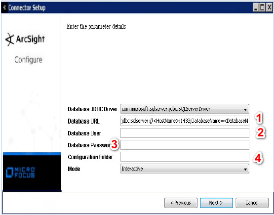
3- Your Setup configuration should be like this:
- jdbc:sqlserver://HRTSERVER:1433;databasename=Test
- username: sa
- password:1234
- Enter the name of the folder that contains the properties file. Do not enter the full path to
the file as doing so will result in an error.
This is also the root name of the configuration file. If the configuration folder is
“myfolder,” the FlexConnector will look for the configuration file in the directory:
myfolder
– The configuration file for time-based connectors will be named:
myfolder.sdktbdatabase.properties
– The configuration file for ID-based connectors will be named:
myfolder.sdkibdatabase.properties
note: Just Enter the name of folder and the name of folder and first portion of properties file should be the name of DB.
Note
After copying the JDBC driver and your properties file, you may get JDBC driver error, so try to close the windows and run the agent from the bin folder. Select Modify Parameters, then enter the information.
4- your configuration file should be like this, don’t forget ? in the query, because it is very important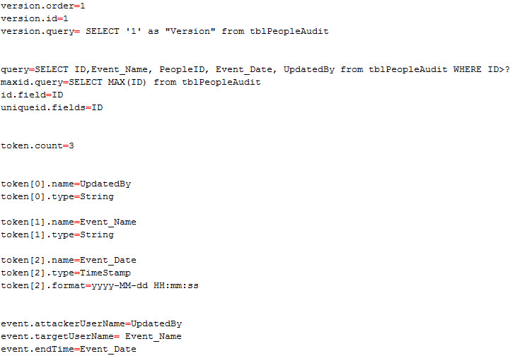
Note
After finishing the wizard, you can see in the process, the name of the service. Usually the name of service starts with the arc_….
DMVPN IKE Call Admission Control
DMVPN IKE Call Admission Control
– To mitigate attack IKE Phase 1 Negotiation
CAC protection
-In Negotiation limit
-SA limit
# show crypto call admission statistics
(config)# crypto call admission limit ike sa 2
(config)# crypto call admission limit ike in-negotiation-sa 10