Do you know anything about SCOM?

System Center Operations Manager has a lot of different features, but what is System Center Operations Manager and how does it work? Well, System Center Operations Manager is a component of the System Center suite, and in our case we’re using the 2016 version. It enables us to monitor services, devices, and operations for many computers and many different types of computing devices in a single console. We can gain quick insight into the state of our environment, and our IT services running across different systems and workloads by using numerous views that show the state, health, and performance information.

It also generates alerts and shows us performance configuration, and security issues. One of the main tools in Operations Manager is our management center computer, and on that particular computer or server, we have a management interface, and it does a lot of different things. One of the things it does is it checks for problems in a management group. In many Operations Manager setups you’re going to see many different management servers, and if there’s any kind of a problem in that management group, then we can find out using that management interface.

We can also start monitoring a computer. This is at the heart of Operations Manager, is monitoring, and we can start monitoring a computer after we push the agent out to our Windows computer, and there are also agentless devices that we can send out to as well. We can create or modify a resource pool. Resource pools are something that we’re going to demonstrate in upcoming videos. We can create a group and give certain rights to those groups, and we can edit those groups as well.

There are lots of predefined security definitions for groups, but we can customize those settings if we desire. We can create or customize a view. There’s lots of different types of views, and some may or may not apply to you, which is why you have the option to do so. There’s event views, there’s state views, performance views, task status views. All different types of views that you can add or delete from your view list.

You can also check the heartbeat status between your management server, other management servers, and your devices. You can also change how often your management server reaches out to other servers and devices to check the heartbeat to make sure the device is up and running. The heartbeat is done using TCP/IP, and a simple ping type request to make sure that the other devices are running and still communicating with our management server. One of the main functions is going to be the rules, monitors, and alerts.

These particular functions give us the main information that we’re looking for when we are monitoring a device. The rules are setup to basically tell us what our thresholds are before we’re going to trigger an alert, and the monitors actually show a graphical representation if those devices have reached those thresholds. We can also use Operations Manager to give users permissions so they can look and see how their device is performing.

In some cases, you may not want this to happen, but in other cases you may have users who require this information to make sure that their device is operating optimally for the job function that they are providing the company. We can also use the tool to investigate a gray agent. A gray agent is an agent that is no longer communicating between the device and the management server, and using the investigation part of the Operations Manager, we can take a look and see why it is no longer communicating.

It could be that the device is offline, or there is a TCP/IP problem, or there is some other issue with the device. Knowing how to utilize Operations Manager can help the IT administrator decide how to best utilize System Center Operations Manager in their network environment.

SCOM- Hamidreza Talebi

Feature of SCOM is:

  • Connection Health
  • Vlan health
  • HSRP group health
  • Port/interface
  • Processor
  • Memory

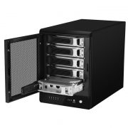
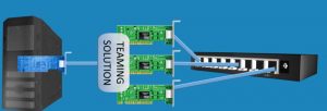
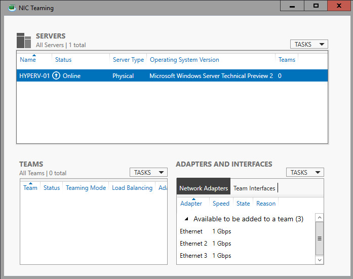
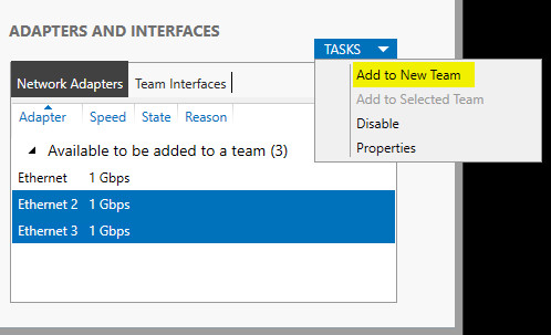
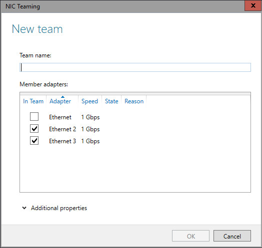
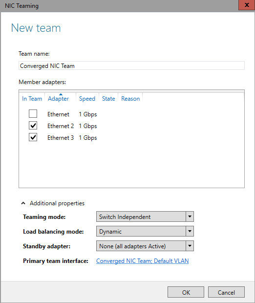
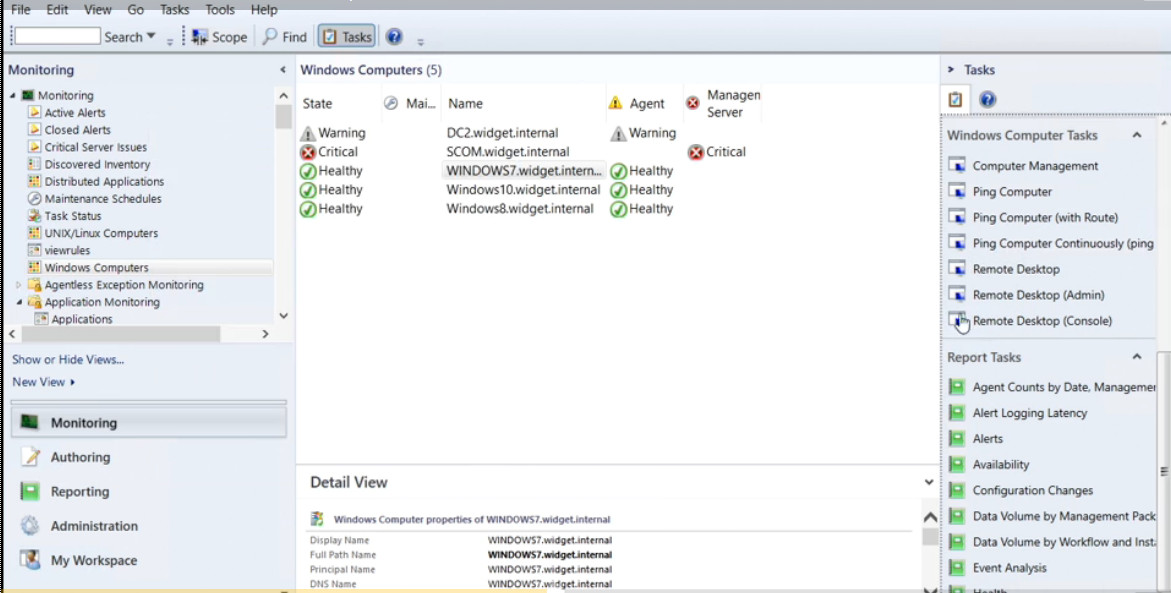
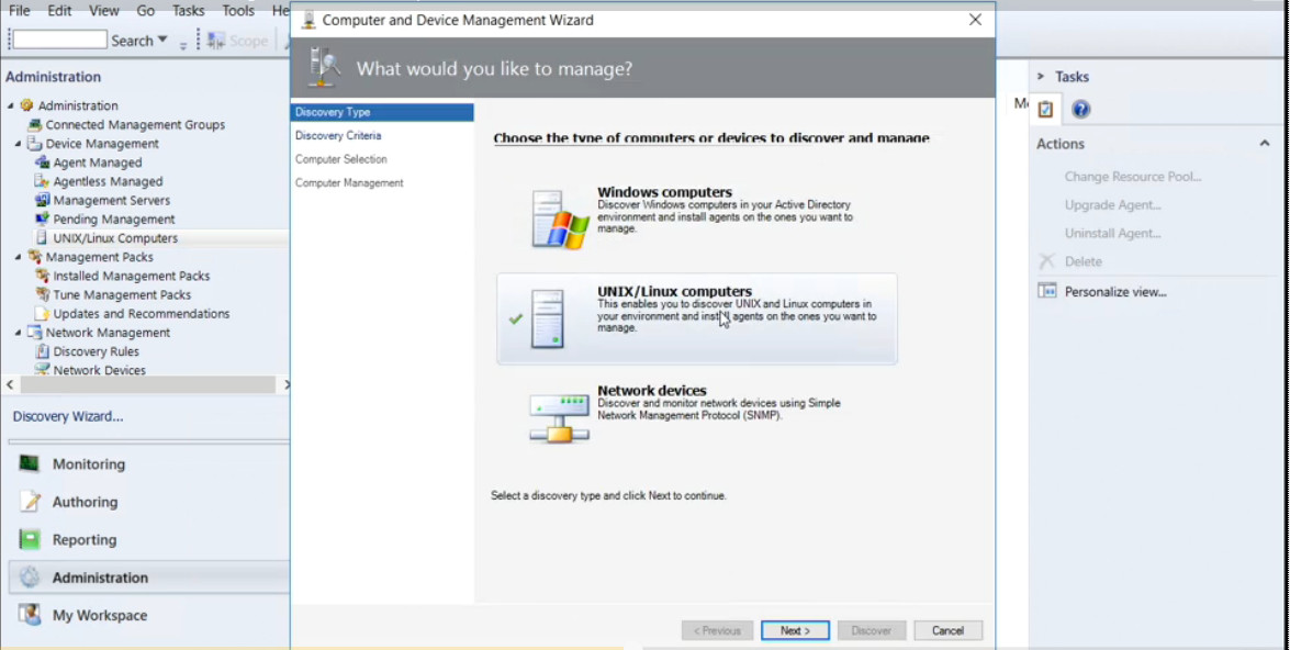
Some pictures of Environment:

Hamidreza Talebi- SCOM

Source: Lynda.com

Show Interfaces and Indexes
netsh interface ipv4 show interfaces

Set IPV4 Address

netsh interface ipv4 set address name=”3″(name of index) source=static address=10.3.66.4 mask=255.255.255.0 gateway=10.3.66.1

Set DNS Address

netsh ipv4 add dnsserver name=”3″ address=10.3.66.3 index=1

Set IPV6 Address

netsh interface ipv6 add address “3” fe80::12:aaa:b:6

Set DNS Address
netsh interface ipv6 add dnsserver “3” address=fe80::12:aaa:b:6 index=1

showing routing
netstat -rn

Changing Computer Name in PowerShell
rename-computer -newname yourcomputerName -restart

Joining Domain in PowerShell

netdom join yourcomputerName /domain:la.com /UserD:administrator /PasswordD:Password


Native file sharing protocols always win out
In an intranet, network clients have several options, such as AFP, NFS and SMB/CIFS, to connect to their file server. But for the best performance, and 100% compatibility, the native client file sharing protocol is the right choice. So AFP is the best protocol for all Mac clients through OS X 10.8, SMB is the standard for Windows clients, and NFS is perfect between UNIX servers. With the release of OS X 10.9 “Mavericks”, Apple fully supports both SMB2 and AFP.

In addition, remote users should be able to securely access server documents via web browser. And mobile users will appreciate a native app for server access and file sharing to their devices.

NFS(Network File Share)
NFS is good for UNIX server-to-server file sharing. However it is incompatible with Windows clients, and is useless for Mac file sharing clients due to missing features, and compatibility and performance problems with Mac apps.

SMB/CIFS (Server Message Block)
The native Windows network file sharing protocol is the preferred protocol for Windows clients.

AFP(Apple Filing Protocol)
AFP is clearly superior to SMB or NFS for Mac OS 8.1-OS X 10.8 clients

AFP is the native file and printer sharing protocol for Macs and it supports many unique Mac attributes that are not supported by other protocols. So for the best performance, and 100% compatibility, AFP should be used.


source: www.helios.de

RAID is an acronym that stands for Redundant Array of Inexpensive or Redundant Array of Independent Disks. RAID is a term used in computing. With RAID, several hard disks are made into one logical disk.

RAID 0 (Strip)

  • Not Fault Tolerant
  • Performance benefit

RAID 1 (mirror)

  • Fault-Tolerant
  • Performance benefit

RAID 5

  • Fault-Tolerant
  • At least 3 disks
  • performance benefit

RAID 6


RAID 10

A partition structure defines how information is structured on the partition, where partitions begin and end, and also the code that is used during startup if a partition is bootable. If you’ve ever partitioned and formatted a disk—or set up a Mac to dual boot Windows—you’ve likely run into the two main partitioning structures: Master Boot Record (MBR) and GUID Partition Table (GPT). GPT is a newer standard and is gradually replacing MBR. GPT brings with it many advantages, but MBR is still the most compatible and is still necessary in some cases. This isn’t a Windows-only standard, by the way—Mac OS X, Linux, and other operating systems can also use GPT.

MBR was first introduced with IBM PC DOS 2.0 in 1983. It’s called Master Boot Record because the MBR is a special boot sector located at the beginning of a drive. This sector contains a boot loader for the installed operating system and information about the drive’s logical partitions. The boot loader is a small bit of code that generally loads the larger boot loader from another partition on a drive. If you have Windows installed, the initial bits of the Windows boot loader reside here—that’s why you may have to repair your MBR if it’s overwritten and Windows won’t start. If you have Linux installed, the GRUB boot loader will typically be located in the MBR.

MBR does have its limitations. For starters, MBR only works with disks up to 2 TB in size. MBR also only supports up to four primary partitions—if you want more, you have to make one of your primary partitions an “extended partition” and create logical partitions inside it. This is a silly little hack and shouldn’t be necessary.

GPT is a newer standard that’s gradually replacing MBR. It’s associated with UEFI, which replaces the clunky old BIOS with something more modern. GPT, in turn, replaces the clunky old MBR partitioning system with something more modern. It’s called GUID Partition Table because every partition on your drive has a “globally unique identifier,” or GUID—a random string so long that every GPT partition on earth likely has its own unique identifier.

GPT doesn’t suffer from MBR’s limits. GPT-based drives can be much larger, with size limits dependent on the operating system and its file systems. GPT also allows for a nearly unlimited number of partitions. Again, the limit here will be your operating system—Windows allows up to 128 partitions on a GPT drive, and you don’t have to create an extended partition to make them work.

totally:

Master Boot Record (MBR) –> 2TB (older os) (32bit)          physical —> Virtual
GUID Partition Table (GPT) –> 16exaByte (64bit) (Repair)         physical -(need tools)–> Virtual


source: howtogeek.com

I have seen some folks who are confused about the concept behind the virtual machine switches. so, I have decided to explain this concept in a simple way:

External : Communicate outside of host (Internet)
Internal: Virtual machine can talk each other and physical host (not Internet)
Private: Just virtual machines can talk each other not physical host

RIP

  • Maximum hop count 15
  • RIP ( 30 Sec update to other routers)
  • Doesn’t analyse traffi
  • Distance Vector
  • RIPng( send through hex to other routers FF2::9)

EIGRP

  • Only to Cisco Protocol
  • Distance vector
  • Analyses traffic
  • Autonomous system limitation
  • Pays attention to bandwidth too. up to 15 routers is good
    in fact, with the same autonomous number routers can speak together. if autonomous number of one of routers is different. The network will be down.

OSPF

  • Larger Network
  • Link state(Dikestra- Shortest path first)
  • Very scalable
  • Uses area instead of autonomous
  • Each area no more 15 routers

Configure rip V2
conf t
(config)# router rip
(config)# version 2
(config)# net 10.1.1.4
(config)# net 192.168.1.0
(config)# no auto-summary

Important command
conf t
(config)# do sh start ( with do that is not necessary to be out)
(config)# do sh ip int br ( good)
(config)# do sh protocols( show protocols )
(config)# do sh controllers ( hardware information)
(config)# do sh ip rip
(config)# do sh ip route

debug ip rip( behind scence)
no debug ip rip

Set IPV6 for
conf t
(config)# ipv6 unicast-routing ( for writing ipv6)
(config)# int f0/0
(config)# ipv6 address 2001:3200….

For IPV6
conf t
(config)# ipv6 router rip 1
(config)# int f0/0
(config)# ipv6 rip 1 enable

sh ipv6 route

RIP timer
router rip timers basic 30(interval between update) 180(Invalid) 180(Holddown) 240(Flush)

conf t
(config)# router eigrp 100(autonomous number can share update in the same autonomous system)
(config)# net 192.168.10.10
(config)# net 10.10.10.0.1
(config)# no auto-summary

conf t
(config)# router ospf 100(process ID)
(config)# net 192.168.1.0 0.0.0.255(inverse subnetmask=wildmask card) area 0
(config)# net 10.1.1.4 0.0.0.3 area 0

show ip ospf neighbour

The Resilient File System (ReFS) is Microsoft’s newest file system, designed to maximize data availability, scale efficiently to large data sets across diverse workloads, and provide data integrity by means of resiliency to corruption. It seeks to address an expanding set of storage scenarios and establish a foundation for future innovations.

Key benefits

Resiliency

ReFS introduces new features that can precisely detect corruptions and also fix those corruptions while remaining online, helping provide increased integrity and availability for your data:

  • Integrity-streams – ReFS uses checksums for metadata and optionally for file data, giving ReFS the ability to reliably detect corruptions.
  • Storage Spaces integration – When used in conjunction with a mirror or parity space, ReFS can automatically repair detected corruptions using the alternate copy of the data provided by Storage Spaces. Repair processes are both localized to the area of corruption and performed online, requiring no volume downtime.
  • Salvaging data – If a volume becomes corrupted and an alternate copy of the corrupted data doesn’t exist, ReFS removes the corrupt data from the namespace. ReFS keeps the volume online while it handles most non-correctable corruptions, but there are rare cases that require ReFS to take the volume offline.
  • Proactive error correction – In addition to validating data before reads and writes, ReFS introduces a data integrity scanner, known as a scrubber. This scrubber periodically scans the volume, identifying latent corruptions and proactively triggering a repair of corrupt data.

The following features are only available on ReFS:

Functionality ReFS NTFS
Block clone Yes No
Sparse VDL Yes No
Real-time tier optimization Yes (on Storage Spaces Direct) No


The following features are unavailable on ReFS at this time:

Functionality ReFS NTFS
File system compression No Yes
File system encryption No Yes
Data Deduplication No Yes
Transactions No Yes
Hard links No Yes
Object IDs No Yes
Short names No Yes
Extended attributes No Yes
Disk quotas No Yes
Bootable No Yes
Supported on removable media No Yes
NTFS storage tiers No Yes

Windows/WinSxS

There is a folder in widnows path that if you have a more than one server, it can use 4G resources. As shown below, your resources may be wasted by this strategy.

So here I am back on our Windows 2016 Server. And I’m going to show you how to remove this Windows side by side directory, reclaim the storage space on the server, and plug this security hole. But I do have one important safety tip before we get started. Do not, under any circumstances, simply delete that side by side directory from your hard drive. It not only contains the files needed to install new features, but it also contains the DLLs and other files needed by features that are already installed.

Just write in a Powershell this command:

Powershell> Get-WindowsFeature | Where-Object -FilterScript{$_.Installed -Eq $FALSE}|Uninstall-WindowsFeature -Remove

Don’t worry! you can install whenever you need these file. But, in installation process it will ask you where is the path of Media to Install?


It it very significant to have a plan for your server. Because some roles in servers have a conflict with another one. Therefore, it is important to know which role uses how much resources. Based on Scott M Burrell research, as I listed below, for example, you cannot use high resources items such as Database and Hyper-V together.

you can download this file to manage your server better. It is a kind of sheet which you can manage your server.

NIC Teaming, also known as load balancing and failover (LBFO), allows multiple network adapters on a computer to be placed into a team for the following purposes:

  • Bandwidth aggregation
  • Traffic fail-over to prevent connectivity loss in the event of a network component failure

You will need at least one adapter, which can be used for separating traffic, that is using Virtual LANs (VLANs). In order to take advantage of the LBFO benefits of NIC Teaming, you will need at least two adapters, and Windows Server 2012 will support up to 32 adapters in a single team.

In Windows server it’s called NIC Teaming, and the purpose is to take multiple physical network controllers and make them appear to Windows as one network interface. Turning on NIC Teaming is simple enough, but you will be asked a few questions that are easier to answer if we take a moment to understand the NIC Teaming environment. So let’s take a look at a couple of scenarios. Consider a file server that is heavily used throughout our network.

Everyone needs to be able to find this file server and this server needs to be able to send large amount of data in different directions at the same time very quickly. The requests from each work station are small enough to not generate a lot of traffic. For this situation it would be nice if all of the traffic to the server could be funneled through the same physical adapter and each client request could be routed through whichever physical NIC was being least used at the time.

NIC Teaming Configuration

Load Balancing Mode

  • Address Hashing
  • Hyper-V port
  • Dynamic

to configure:


  1. In Server Manager, click Local Server.
  2. In the Properties pane locate NIC Teaming, and then click the link Disabled to the right. The NIC Teaming dialog box opens.

3. In Adapters and Interfaces, select the network adapters that you want to add to a NIC Team.

4.Click TASKS, and then click Add to New Team.